
One thing I have noticed in perusing the JPI Engine data is that the left engine cylinder #4 has been running significantly hotter than any other. That could be due to the break-in not being completed, or it may indicate the need to fine tune the new GAMI injectors to a tighter fuel flow spread.Of course, this could all be entirely normal, or it could be something else I haven’t yet considered.
In order to evaluate each engines GAMI spread, and thus eliminate injectors from further evaluation in the case of the hot LC4, I will be conducting a GAMI Lean Test on the airplane. Since this involves determining peak EGTs for each engine, and thus successively leaning each one, care must be taken so has not to abuse the cylinders as the data is gathered. This is where the GAMI technique is combined with the Red Fin concept and LOP leaning techniques to keep me safe.
I am relying on several resources to help me prepare for this upcoming flight. Mike B, (not Busch) regularly flies Cirrus aircraft and introduced me to LOP and the Red Fin. He is my other set of eyes on this data and my understanding of it. Mike Busch is the author of ‘Mike Busch on Engines’, which has been my source for understanding the leaning process of non-turbocharged, fuel injected engines. He has a video tutorial on the break-in process which I’ve studied more than once. Finally, the GAMI fuel injector website has information on conducting the test and the company has offered to analyze the results once complete.
Background: N833DF has ‘new’ engines, and I’m uncertain as to whether the break-in process is complete or not. Per the collective wisdom, stabilized oil consumption and/or a clear drop in CHT per cylinder would indicate that break-in has occurred. I didn’t believe that would be obvious when I read about it, and I certainly haven’t seen indications of that in the data. I am not putting much faith in my ability to see a clear delineation of either variable with this approach.
Penn Yan overhauled these engines and says that engine break-in can take as little as 10 hours or as long as 100 hours. They tell you that stabilization of oil consumption is the key to knowing when your engine is broken in. They don’t mention CHTs at all. They’d like to see 75% power the entire time, and no touch and goes for first 30 hours. This is actionable advice.
Mike Busch says to watch CHT for a clear drop of 20-40o that would indicate break-in has occurred? I doubted from the outset that I’d see an indication like this, and I haven’t. Too many variables and too simplistic an approach. In his video on engine break-in, Busch says to allow up to 440o during the break-in for Lycoming engines. Note that he also states in one document that your should operate Lycoming engines up to 380o, and in another up to 420o normally. That is a considerable range and difficult for an engineer’s mind to apply. Still another reference calls for 400o as the maximum CHT.
Detecting CHT drops: I ran the engines hard the first 10 hours, allowing LC4 to get to as high as 430o. After the 10 hours, I limited myself to 75% power and 400o on any cylinder on the assumption that break-in may have occurred and I’m not aware of it. The weather and I have been inconsistent, so the CHT drop may have been masked. In retrospect, it would have been good to have recorded Pressure Altitude, MP, OAT, RPM, and Cowl Position for each flight. I’ll do that on subsequent flights if I can manage it single handed.
I’ll start off the GAMI test flight with a period of time at full power; full rich, cowls open at 2000′. I’ll compare that with the first flight on 2/19/2020 with the same parameters at 2o OAT and see if I can detect any CHT drops between the two.
Detecting oil consumption stabilization: How the hell would I be able to detect that already? I put 1 quart in during the first 10 hours, which is no surprise given that I was running around balls-to-the-wall the entire time.The general advice is to precisely position the aircraft in the same spot on the hangar each time, and measure the oil consumption each day. Measure with a micrometer, mark with a chalk line, and cut it with an axe. This is an approach that is just silly, in my mind. No way you can be accurate. I’ll measure it in 10 hour increments instead, thought I’ll obviously check it every flight. Pointless exercise for now.
That means I have no idea if these engines are through the break-in process or not. The engines are running well and developing excellent power. Fuel consumption is up, but my flying pattern is completely different. Nothing to see here, so let’s focus on LC4 being at a high CHT and go find out what our GAMI injectors are doing.
Current operating philosophy is to continue to use only high power settings (except for the short period I’ll run this test); keep all CHTs under 400o; cowl flaps open or closed based on CHT; and lean no further than 10 GPH while at full power. I do not know where peak EGT is at 75% power. Minimize low power operations. The 10 GPH leaning may be changed based on what I learn during the test.
Leaning is a very good thing, unless you do it incorrectly. Then it can be bad. Really bad. I’ll be revisiting this subject once I’m sure break-in is completed, and begin to operate LOP and ROP.
Mike Busch (paraphrased): High CHTs often indicate that the engine is under excessive stress, which is why it’s so important to limit CHTs to a tolerable value (no more than 400°F for Continentals and 420°F for Lycomings). High EGTs do not represent a threat to cylinder longevity the way high CHTs do. Therefore, limiting EGTs in an attempt to be “kind to the engine” is simply misguided.
EGTs are expected to be different (JPI DIFF measurement). It is not uncommon for well-balanced fuel injected engines to exhibit EGT spreads of 100°F. In fact, EGT spreads are usually smallest near or just rich of peak EGT (the worst place to operate the engine), and often significantly greater at leaner or richer mixtures (that are much kinder to the engine).
The mark of a well-balanced engine is not a small EGT spread (“DIFF”), but rather a small “GAMI spread”—defined as the difference in fuel flows at which the various cylinders reach peak EGT. Ideally, we would like to see this spread be no more than about 0.5 GPH (or 3 PPH). Experience shows that if the GAMI spread is much more than that, the engine is unlikely to run smoothly with LOP mixtures.
There is no such thing as a maximum EGT limit or red-line, and trying to keep absolute EGTs below some particular value—or even worse, leaning to a particular absolute EGT value—is simply wrongheaded.
50°F ROP is almost precisely the WORST possible mixture setting from the standpoint of engine longevity. The maximum cylinder head temperature (CHT) and peak internal cylinder pressure (ICP) occurs almost precisely at 50°F ROP. The hottest, most stressful mixture is about 50°F ROP, and mixtures that are richer OR leaner are better for the engine.
At 75% cruise power, you want to stay well away from that worst-case mixture setting, either by operating at least 100°F ROP (preferably richer) or at least 20°F LOP (preferably leaner), take your pick.
Mike Busch’s leaning technique – paraphrased
- Generally, cruise LOP to be cooler, cleaner, cheaper, greener
- Don’t use EGT as a leaning reference for cruise flight. Absolute EGT values are meaningless. Determining peak EGT by leaning very slowly puts the engine in the area of maximum stress and ICP routinely. This is a Lean-Find approach.
- Do I want to go fast (i.e., achieve maximum airspeed) or do I want to go far (i.e., achieve minimum fuel consumption)?
- For modern airplanes like the Cessna TTx or Cirrus SR22 or Diamond DA40 with their superior engine cooling systems, those target values should be reduced by about 20°F.
- In cold OATs (below ISA), the CHT targets should also be lowered a bit.
- Fast: Lean so that the CHT of my hottest-running cylinder does not exceed 400°F for Lycomings. Does this imply that you can do this ROP without knowing where you are in terms of peak EGT???
- Far:Conversely, if the hottest CHT is lower than the target value, I can gain a bit more fuel economy by leaning a bit more (if ROP) or a bit more speed by richening a bit more (if LOP). Best economy occurs at Peak EGT. You’ll fly slower but further.
The Red Fin
Defines an area or zone of operation where we should not be. Note that the GAMI Lean Test calls for 65% power being used, and that is the very tip of the dark (danger) fin on the right. They recommend less power if the CHTs get up close to 400o as well. The GAMI test will determine where peak EGT is for every cylinder at 65% power. This graph relies on the first cylinder in each engine to peak.
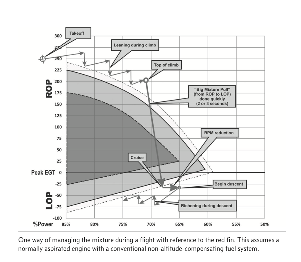 [Again – extracting from Mike’s book] Busch recommends NOT using the “lean-find mode” of your engine monitor when doing this [leaning], because this requires you to lean very slowly to locate peak EGT. That results in spending a considerable amount time inside the red fin (and the dreaded purple zone), which is exactly what you don’t want to do.
When we reach top-of-climb, level off, and commence the cruise phase of the flight, we perform a “big mixture pull” (BMP) to transition from ROP to LOP. This should be done quickly to minimize the amount of time spent inside the red fin (and especially the ultra-abusive purple zone). About 2 or 3 seconds is about right for the BMP. Note that we lose a bit of power as we transition from ROP to LOP; that’s normal and expected, and will be reflected by a small loss of airspeed.
One question for Mike Busch – you say you don’t have any idea how far from Peak EGT you operate LOP, but at the same time, recommend at least 20o LOP for us. I’d say you have two methods for LOP. The first would be to manage CHT on the peak cylinder and assume that will give you better than 20o LOP. The second would be to precisely measure peak EGT from the lean side, and choose something greater (leaner) than 20o LOP. I found the answer in his book…..
Busch continues: If you feel compelled to locate peak EGT, it’s much better to perform a quick BMP to get into the LOP zone below the fin, and then slowly richen to locate peak EGT from the lean side. Personally, I don’t care about locating peak EGT, so I skip this step altogether. I just do a quick BMP to a known-safe LOP fuel flow—or until I hear and feel a small power loss that tells me I’m safely LOP below the fin—and then fine-tune the mixture using either CHT or my fuel totalizer as a primary reference.
Profile for the GAMI test
- Fly a period of time replicating first flight / CHT comparison
- Mixture Full Rich
- Cowl Flaps Open
- 75% power or better – high as possible
- Record Pressure Altitude, OAT, RPM, MP
- Pick up Safety pilot 33N if available
- Brief safety pilot duties
- Safety information
- Purpose of the flight today: Develop lean test data for GAMI engineers
- Electro-air ignitors
- GAMI injectors
- Handle radio as necessary
- Monitor legs page / planned route
- Navigate clear of airspace in pre-defined pattern
- Watch for traffic
- Monitor auto-pilot
- Maintain directional during repeated asymmetric thrust scenarios
- Don’t use rudder trim due to continuous change expected
- Be prepared for engine failure / unexpected power loss
- Climb to 3,500’ and check one engine at a time
- Set power 22.5” MP / 2300 RPM (65%)
- Record Pressure Altitude, OAT, RPM, MP, Oil Pressure
- Auto-pilot on following route
- JPI: Set FF/All/EGT switch to EGT for engine only data
- JPI: Set MANUAL Indexing and cycle to Cylinder #4, the highest CHT
- JPI: Still in MANUAL, Set FF/All/EGT switch to FF. Cycle through to display FF.
- This will allow toggling back and forth to check CHT #4 as necessary, and fuel flow in progress
- Lean the right engine to roughness (big pull) and richen to smooth operation.
- Move mixture such that it takes 2-3 secs to accomplish
- Note Fuel Flow
- Set FF/All/EGT switch back to EGT; monitor CHT
- Monitor CHTs and wait one minute to stabilize
- Use JPI toggle switch to check on CHT #4 either engine (hottest), and then back to Fuel Flow
- Slowly enrichen the mixture at 0.2 GPH increments (to allow data capture)
- Toggle between CHT #4 below 400o increasing Fuel Flow at 0.2 GPH increments.
- CHT shouldn’t be an issue doing this from the lean side and at reduced power (65%), but I’ll stop the test and reduce power if it is. Note that the Red Fin as it’s tip at 65%.
- Monitor all 4 EGTs on the bar graph until seeing them all moving down
- Restore mixture to 10 GPH
Fly Safe!
Frank